
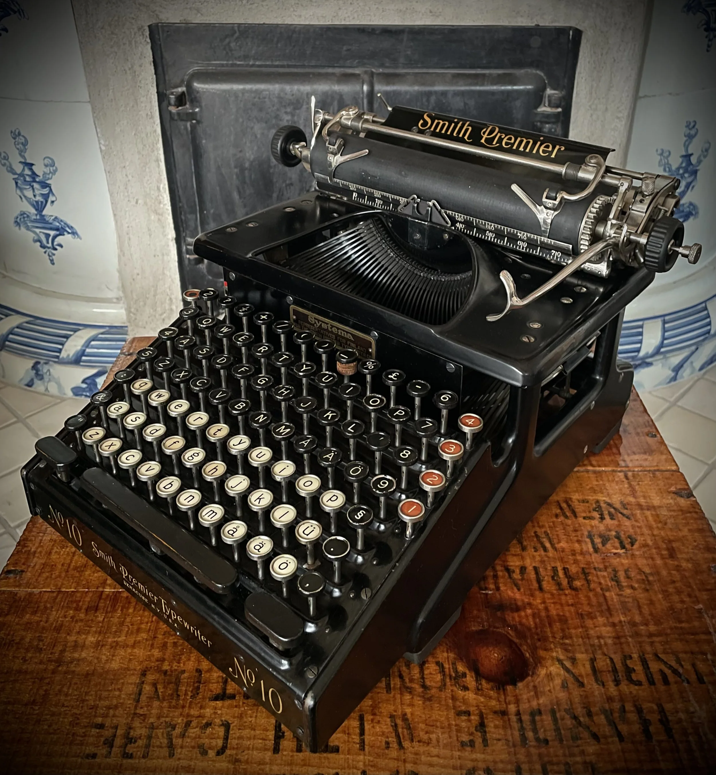
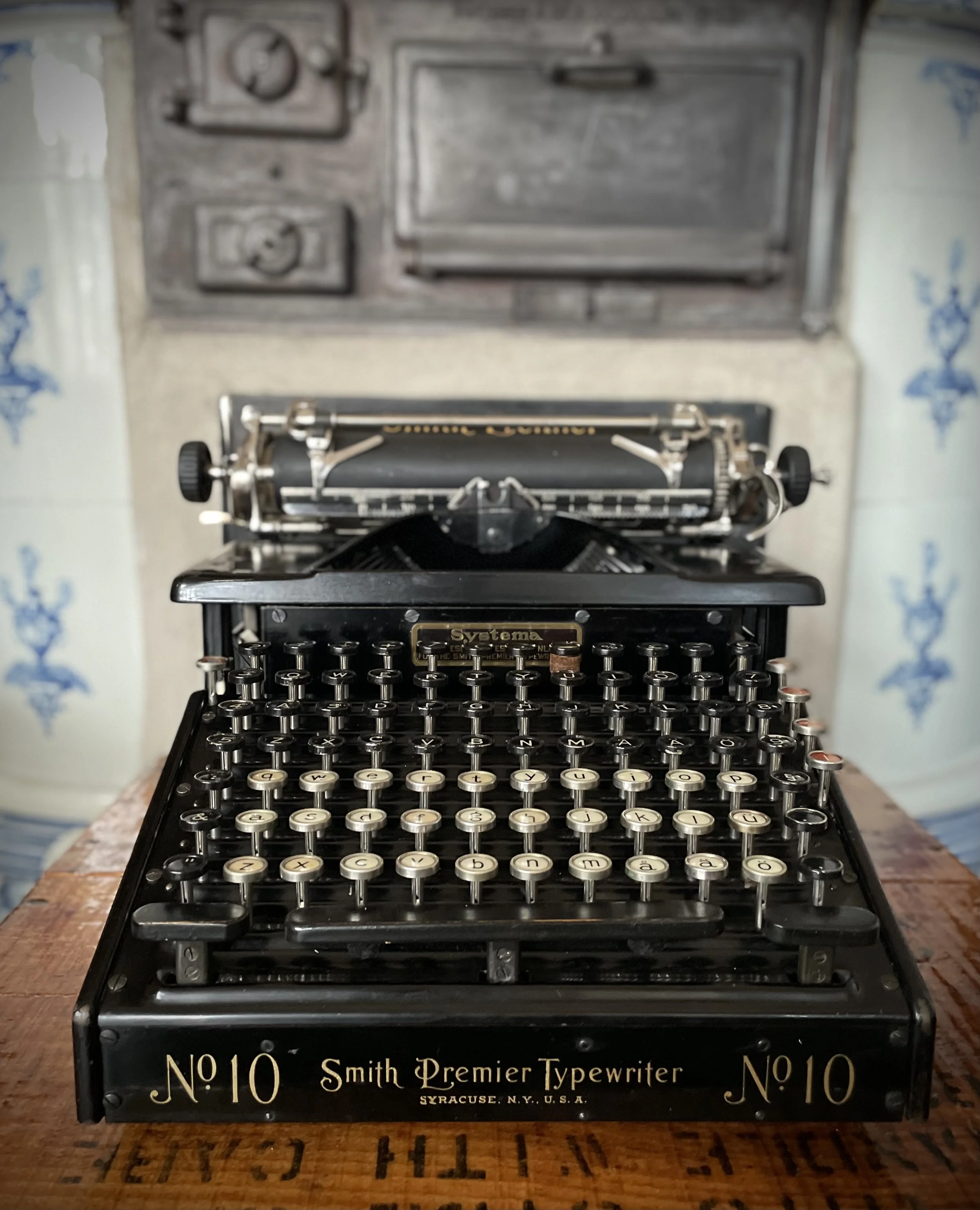
Smith Premier 10 aka "cash register"
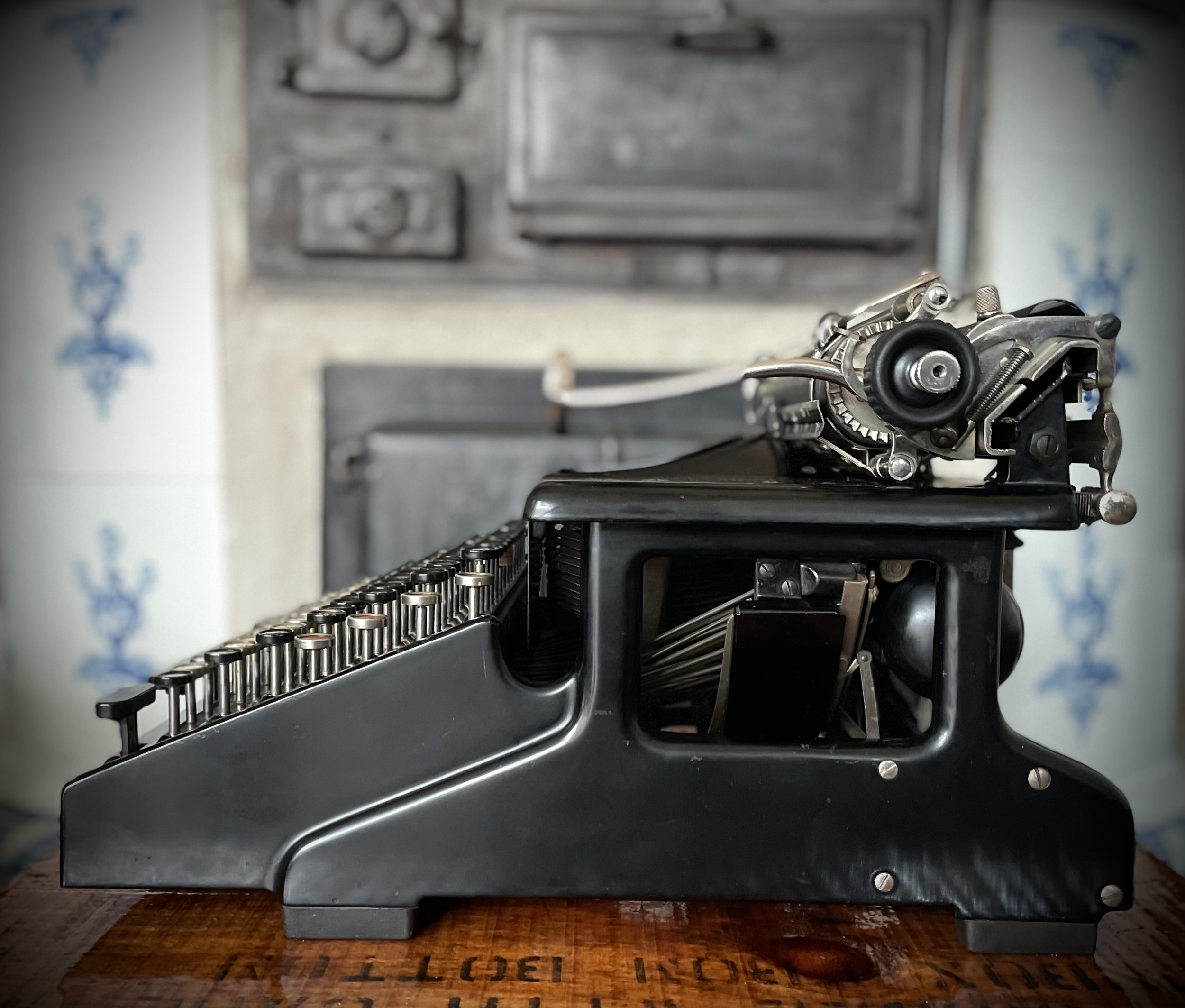
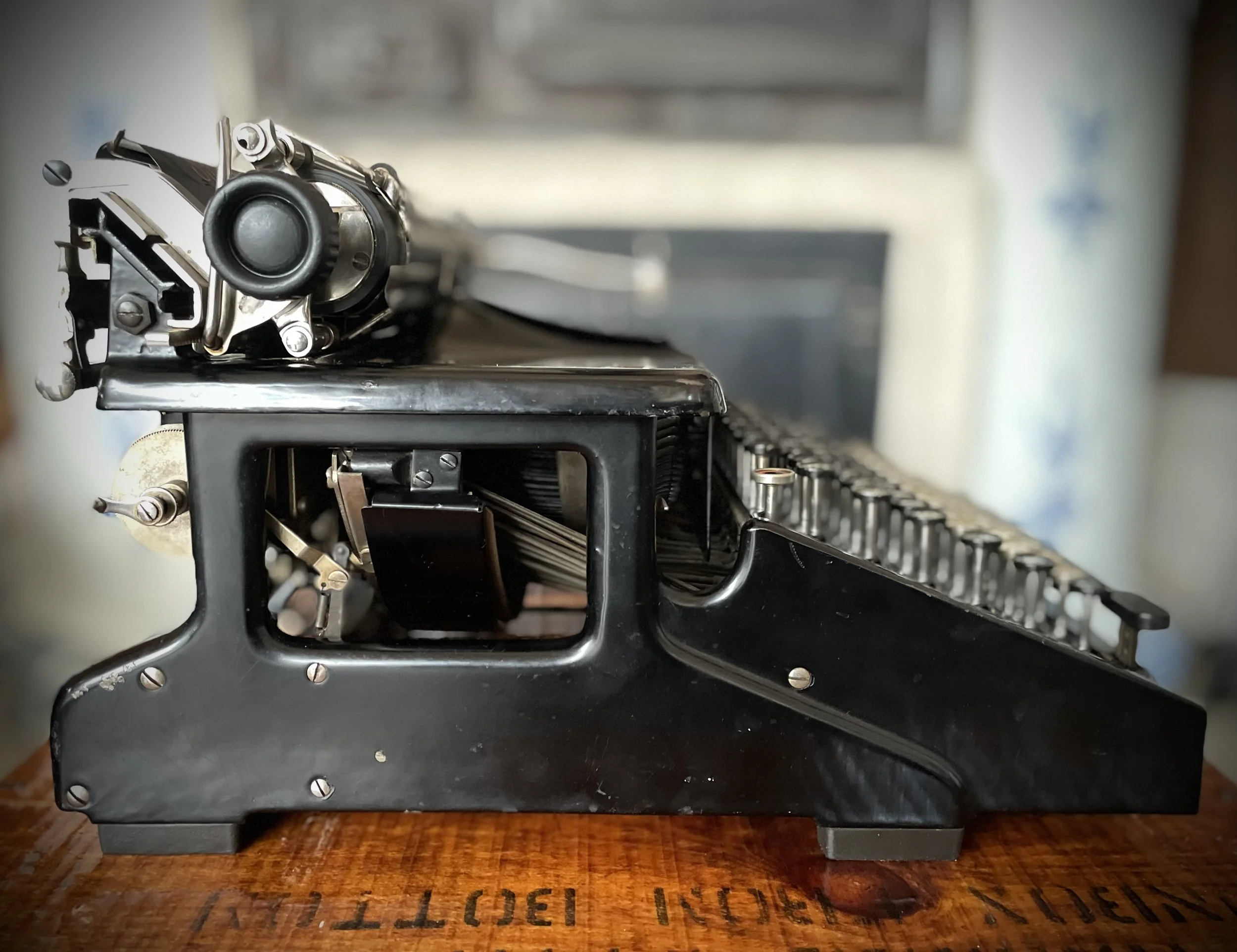
I guess we are lucky here, in Sweden: these machines are not liked, most collectors or ordinary people consider them ugly and unnecessary big. As long as the first point is indisputable (taste) the second is a misconception. If one see only a photo of this machine, with double keyboard, it is easy to get that impression. But in real life they are not bigger than any standard typewriter. In fact they “feel” smaller because of their wedge-like shape and open construction.
A bit like Royal 5 “flatbed”.
Anyway - as they are not sought after, when they pop up they are cheap so I could get two machines for very little money. One was in good, almost working condition. The other was beaten and rusty - it became a donor and a “guinea pig”.
Without fear of damaging my “keeper machine” I put apart the donor, harvesting all parts I may need. First come the keys - they are easy to pop out, sitting in their open-tubes just with friction and small extrusion which prevents them from turning around. Clever design and easy to work with.
It is tempting to unscrew the top plate for easier cleaning and waxing, like I did on Flatbed. One should restrain this temptation - there will be a heck of the job to put it back!
The plate itself is also a quite sophisticated subassembly. Luckily it usually is not that dirty as it sits up-side-down. With all these felt pads and clamps it could gather lots of smelly dirt if sitting somewhere in hens-house.
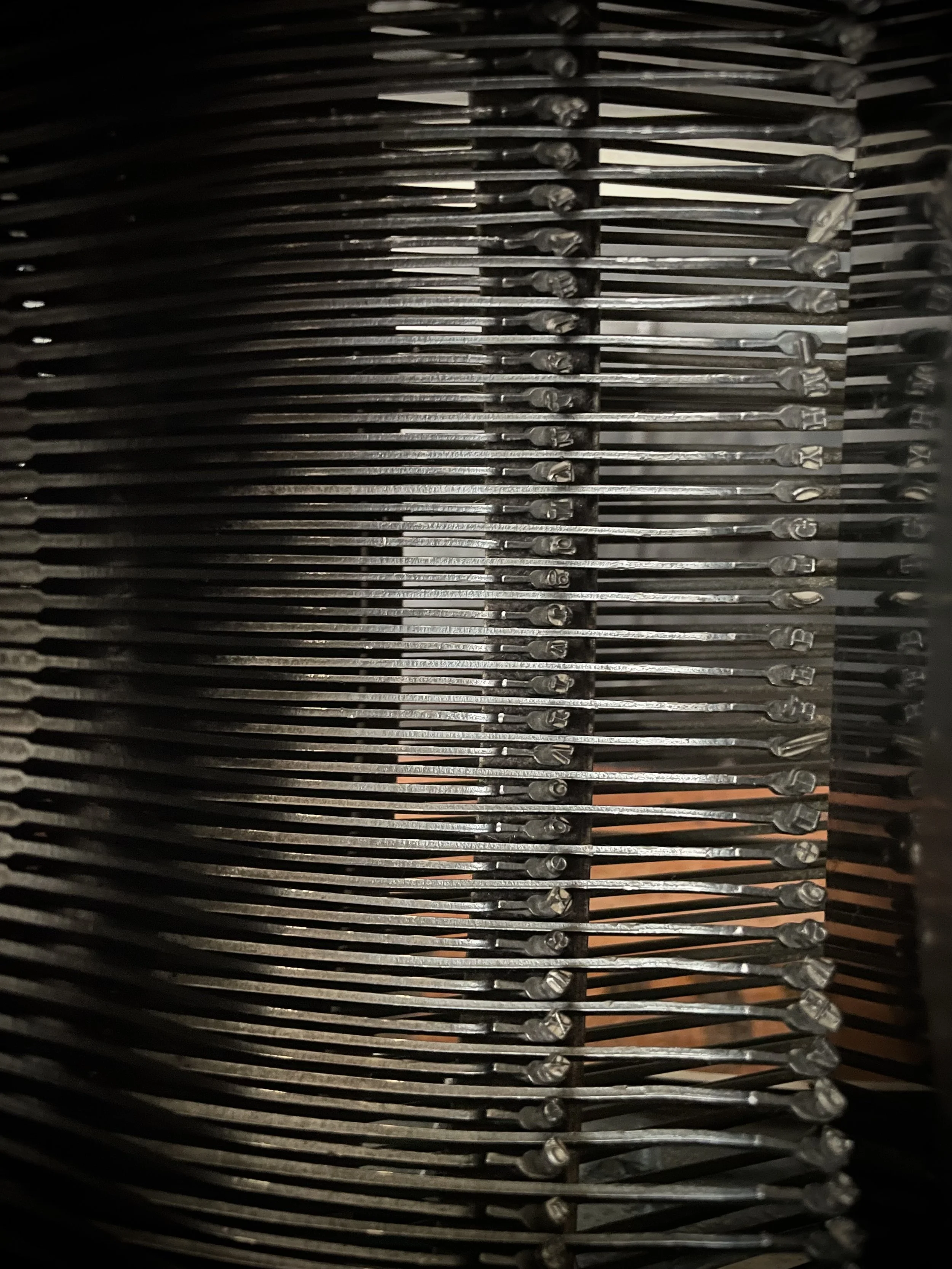
Type arms on this machine are hanged on ball bearings. As there is one sign per slug, and per arm, there are a lot of bearings organized cleverly in two rows.
It must have been expensive to manufacture these arms for sure. I admire delicate form of these parts!
Actuator springs for each arm are smartly hidden under the bent, steel cover, protecting them from dirt and unintentional decoupling.
Type arms are anchored in middle-segment by hooks, not thru-axis. I suspect it was caused by this large amount of elements to accommodate there, it would be a challenge to thread them all through when assembling the machine.
Feed rollers are easily accessible if one needs to work on them. After the carriage is removed (very easily, no tools required) one needs to just unscrew the cover plate.
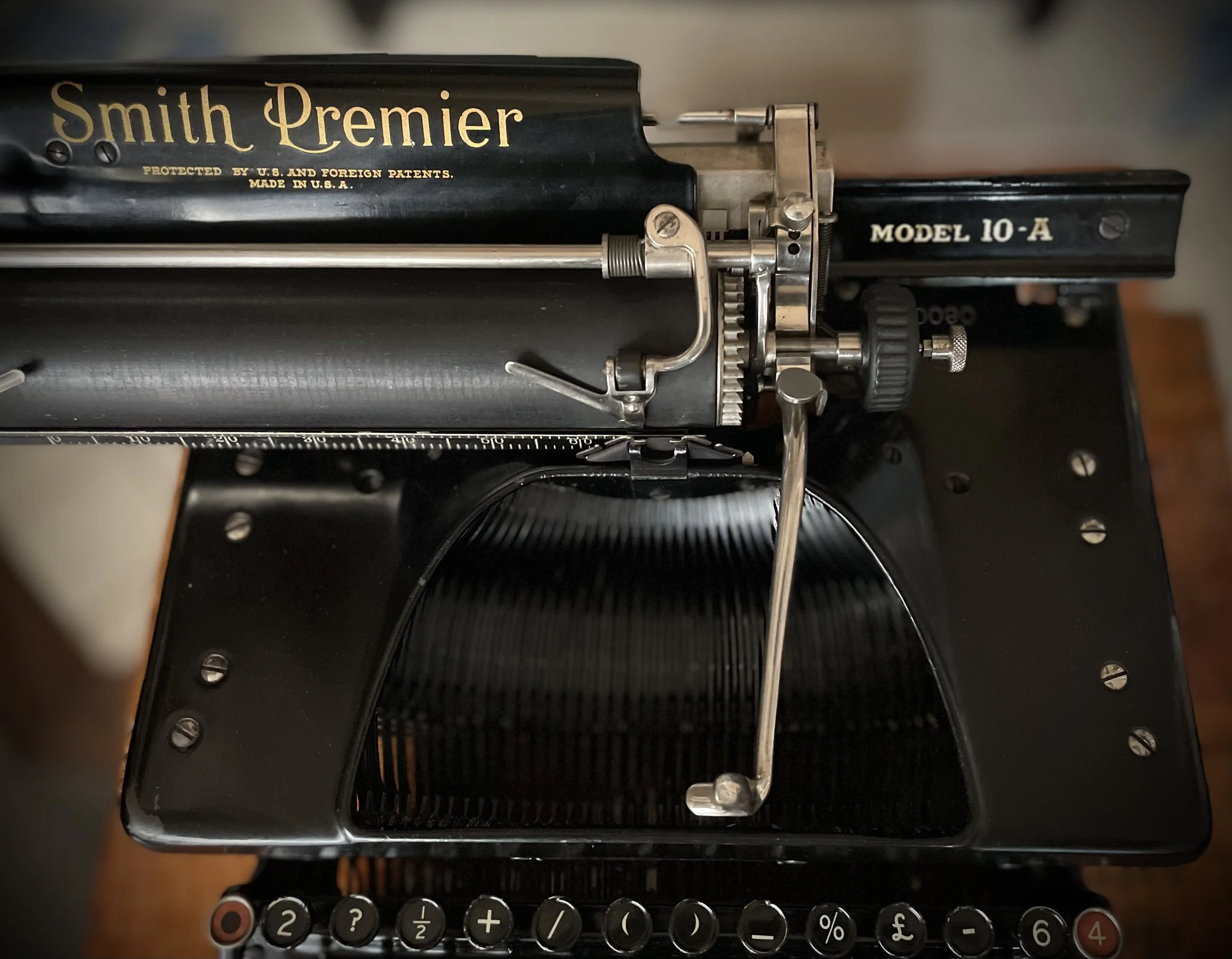
Small rollers sit on common axis. Knurled end of this axis suggest that it shall be pulled out as red arrow points below.
Similar procedure for big, back rollers. Easy.
This machine has an interesting tabulator mechanism. Basically one has 4 tabulator settings on rotatable single tabulator bar, with tabs formed to engage with one of four prongs related to specific “tabulator program”. Good explanation of this is given by Geir on his channel here.
Another intriguing design within this system is tabulator brake. It consists of a bottle filled with graphite powder - at least today it is a powder, we speculate that it may be that it was a thick paste, oil-based, when the machine was new. But it works anyhow even if it is a powder now.
Wire-propeller inside the bottle is connected to tooth-wheel and by compressed powder friction is able to slow down the carriage when it flies to the next tab-stop.
Compression of the powder is adjusted by a big nut (yellow arrow), small screw (green arrow) is locking the position.
Carriage glides on four sets of bearings. On my machine one of these bearings was empty - all three balls were out. That was causing uneven movement and rattling. There was also something holding the carriage at the very end of its travel.
Stop positions for both sides are done with small extrusions on both sides.
Screw which engages with them is close to small wheel which in turns glides on two sets of toothed rails beneath. To protect it from damage and easier work I unscrewed it.
With these removed one can easily slide the carriage rail beyond its end-position, to expose ball bearings. If done carefully balls will stay in place, especially if one angles the assembly so that good-old gravitation keeps them in place. Here the top-bearing is visible, void of balls.
Stop screw which should engage with carriage end positions gave a hint what happened with the carriage bearings. This screw now being too short caused carriage to “jump” at the end position and end up jammed on the stop extrusion.
Clearly it was sheered and judging from metal color it was not long ago. I replaced it with one from my donor-machine.
With the machine clean and working I had one last detail to attend: line spacing clutch mechanism. It is working but the axis was missing its chromed knob, leaving just small nuts to protect fingers from pain.
I found some spare knob from more or less same era and drilled one end of it to accommodate the nut.
Press-fitted the nut and voila!
I added the second nut to be able to lock it in position.
Traditional photo session follows.
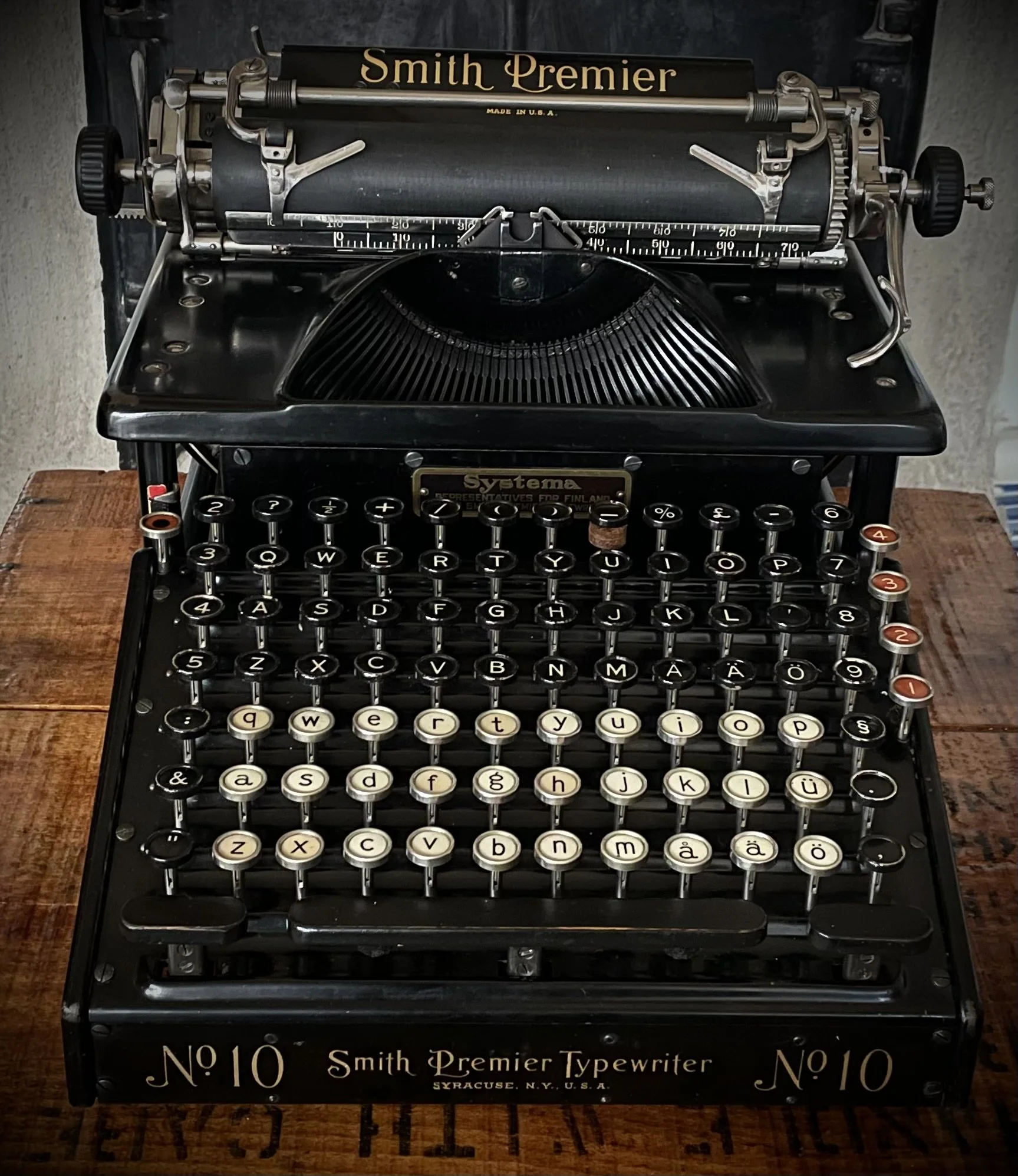
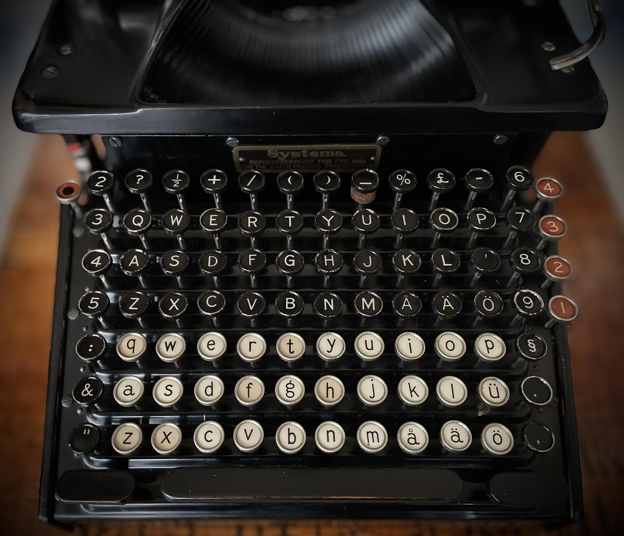
Keyboard controls:
Some features on the back of the machine. Ribbon reverse is done within cranking handle on the side but can also be directly steered between the spools.
Ribbon threading is a bit more tedious than usually. Below is a picture of how it should look. Good description and way of doing it can be found on Brian’s video.
Type slugs, one per arm, sit by friction fit only. My machine had missing some so donor specimen came to help.
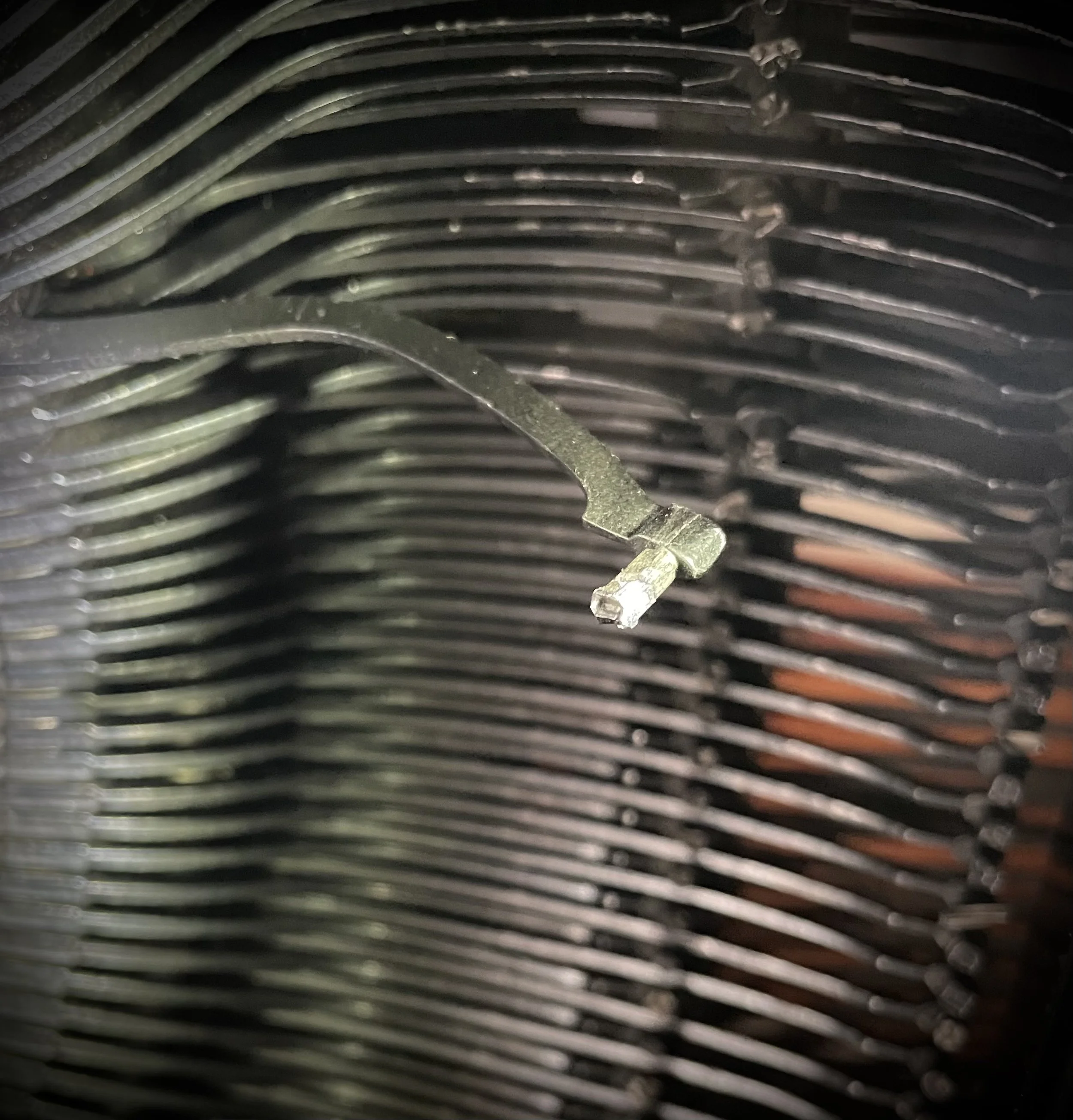
Type-alignment is perfect.
Typing feel is very good, in the same class as Royal 5. Definitely a machine which can be used for serious typing even in our times.
My machine came with a bit oversized steel-hood and poorly-preserved wooden base-board.
Top veneer was held in place only by screws and fittings, warped and water-damaged otherwise.
Bottom part had its veneer gone, exposing wooden slats and machine-holding screw wells.
Things were held together by friction only, the glue has since long turned into dust.
At first I thought of moving the fittings to a new board which I planned to fabricate but after removing the top veneer I decided better of it.
It´s never too late to give up.
Why not try and preserve this original board, shall we?
Top veneer removed, fittings unscrewed and brushed from rust clean. Some apparent mishaps in manufacturing of this board are now seen once veneer is gone.
Taken out for sanding and cleaning joints from the old glue.
Reassembled to mask-tape vicinity of areas to be glued.
I also plugged unnecessary holes someone chose to drill in this beautiful, old-growth oak from the last century.
A day later the glue is cured, the board cleaned and sanded again, ready for stabilizing soaking in epoxy.
Once all was cured, cleaned and reassembled again the machine has its baseboard back and rocking!
Bolts to attach the board to the machine were gone but I found that M5 bolts fit perfectly to this otherwise imperial-threaded holes. Happy coincidence.
With this little accent I consider the restoration to be finished, for now.