Boatworks

  • Main
  • Louve
  • Typewriters
  • Workshop
  • Meritaten
  • Glypto
  • Motoko
  • Inspirations
  • About
IMG_6035.JPG

Engine bed and lead pancakes

April 01, 2019 by Lukasz Kumanowski

Time is running out so I returned to my evening visits in the boatyard. A bit of the job done during these few hours really makes a difference in the end.

One of the quick jobs is to fix the left part of the engine foundation. It’s an ancient piece of oak - apparently it was originally shaped for Albin gasoline engine which was then replaced in the 90’ by my current Yanmar diesel - which required addition of steel rails with rubber pillows dampening diesel’s vibrations.

One part which meets the rib and hull on port side has weak oak - it is soft and easily gives way to a needle. It has to be replaced.

IMG_6036.JPG

I see that it was glued before - apparently the oak was of not best quality because it rotted again. I cut it out above the old glue line for replacing with laminated oak.

IMG_6038.JPG

After gluing the part will be shaped to match the hull. Then the whole foundation will be painted to finish the renovation.

At some point I will need to make new engine bed - probably when old Yanmar dies and I will switch to electrical engine. Hopefully not soon but that is the plan today.

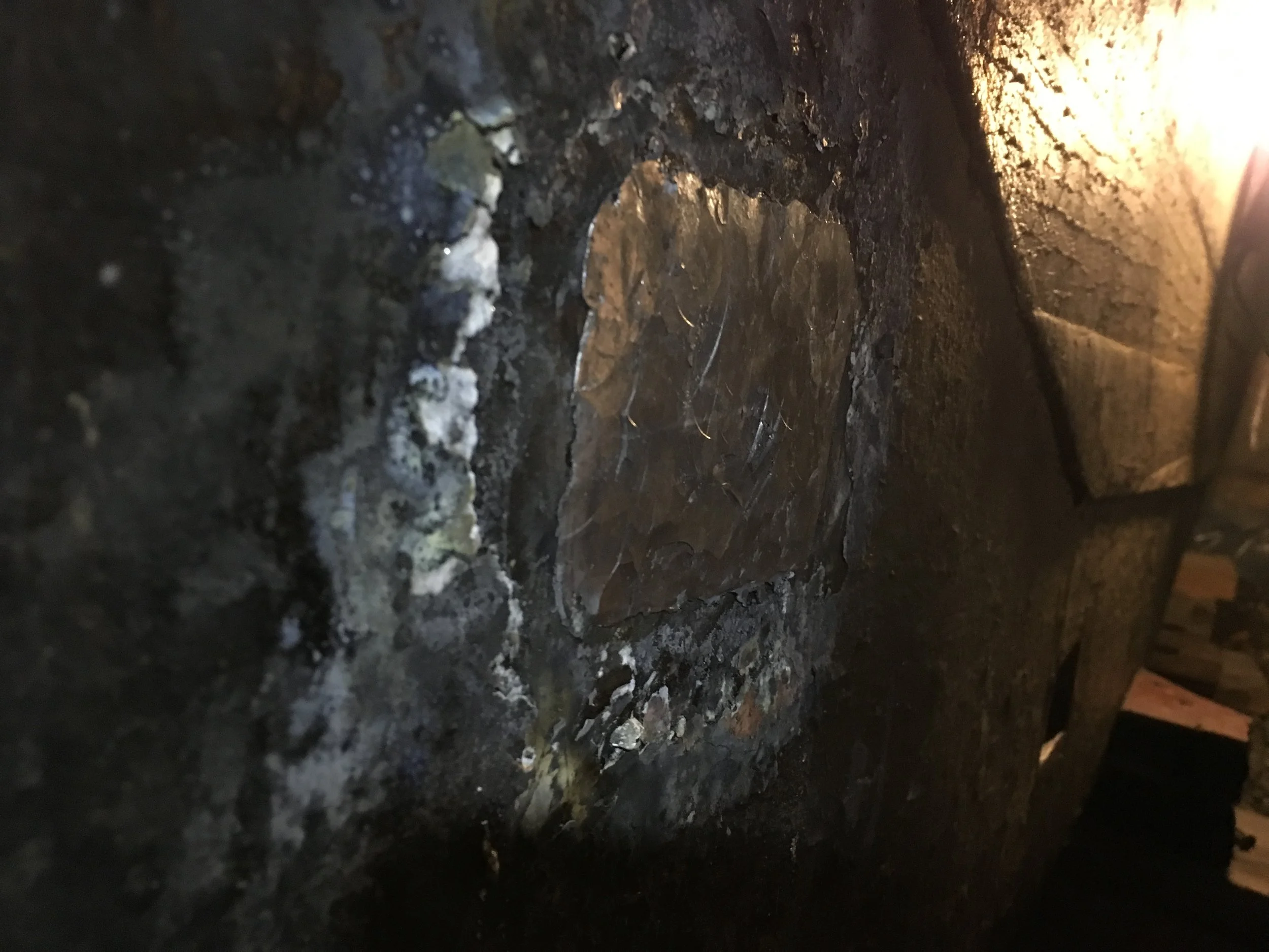
I moved to remaining lead plugs which shall close ballast openings. Same story as with the first one: initial shaping with chisels and hammering into the hole as much as it goes.
Börje says I’m crazy to do that, he would never put this lead back - too much hassle and not much weight benefit. I agree with him but since I’m half-way now and since I’ve put so much effort into this then I’ll continue anyhow. His suggestion is to shape a piece of oak and put it instead, with Sika as a sealer. That certainly works too.

Anyway - swinging the hammer, sweating and heavy breathing through gas mask, melting lead with MAPP torch, hammering again on soften, hot lead - that was my evening. In the end I got nice, big lead pancake.

IMG_6040.JPG

Some more shaping with flame and finally the second opening is closed!

IMG_6043.JPG

Iron oxide primer will follow, then some Farm liquid rubber, just to be sure there is no leaking into the opening and finally bottom paint.

I could use less work-heavy way of shaping remaining lead - with angle grinder - but that would mean lots of noise and lead dust everywhere. Instead - with a torch - I can gather all excess lead into a pot. I will use it to cast an anchor “pig”, to be mounted on anchor line for optimising holding angle.

IMG_6044.JPG

If all goes well then tomorrow night I will close the third opening and this job will be finished.

April 01, 2019 /Lukasz Kumanowski
Comment
IMG_6019.JPG

Floor timber, keel bolt#3, frame scarf

March 29, 2019 by Lukasz Kumanowski

I took a day off from payed job to catch up with Meritaten’s renovation. Rosättra boatyard has started to put boats into water today - ice has melt, 10 degrees on plus, sunny and strong wind.

The list of tasks for today was long but I ended up doing only one of them, for the whole day: installing floor timber #3.
It was a combo-job: before installing the floors I wanted to remove broken frame and shape a scarf for gluing the new bit. Much easier done if the floor timber is not yet installed, otherwise I cannot access this with a hand saw.

This frame is originally glued from 5 pieces of bent oak. I am repairing it with my glued/bent frame consisting of 15 thin pieces.

After measurements I cut the first incisions to prepare a glue joint. The 5 elements of this frame - originally glued - are no longer glued to each other. The glue is gone. After removing all the rivets and screws (brass !!??) I am starting to shape the joint for replacement part.

FullSizeRender.jpg

Hand saw, chisels and angle grinder. Last step with hand plane to plane the scarf.

IMG_6025.JPG

The next step was to adjust the shape of the new frame bit to the hull and to the planned joint. The dimensions were transferred with respect to aft and fore face of the old frame, to accommodate hull’s curvature in both directions.

IMG_6026.JPG

Once I was happy with all faces alignment I could finally install the floor timber. Freeboard was soaked in linseed oil few days ago and got some more today.
The bottom face and all end grain of the new floor timber was sealed with penetrating epoxy and then painted with iron oxide paint, the traditional way. Upon installation I spread bedding compound - Farm 80 - to close all possible gaps between freeboard and floors.

IMG_6028.JPG

The component went into its place and new keel bolt #3 followed.
The bolt was painted with epoxy as a rust protection. As additional sealing I’ve covered it now with the same bedding compound.
It has three functions here: close gaps, if any, in the keel hole, minimise friction upon installation (hammering into tight hole) and to isolate the bolt from oak.
Additionally it will keep it from being glued to the structure as I needed to correct my mistake in drilling the hole in new floor timber.

IMG_6030.JPG

Due to my drilling error I ended up with the hole which was oval-shaped, leaving a gap between the bolt and wood on both ends of the new floor timber.
Now, with keel bolt inserted, I filled this gap with thin epoxy until it started to flow in the bilge. Upon that I tightened the nut and pressed down the floor timber so that it “sat” in its place entirely, closing all gaps with squeezed-out bedding compound.

In the iron keel there are again 2 nuts, on the floor timber there is one. Big and thick steel washer which I made for this element spreads the load more evenly than washers in the old floors.

IMG_6032.JPG

There is still a bit of bedding compound to be cleaned but I will do that tomorrow, when it dries a bit.

What is left now, on this part, is to close the ballast opening with lead plug and to rivet and screw adjacent frames and freeboard planks to this new floor timber. Of course I will use silicon bronze screws, not brass as original.
Then I will final-shape the new frame bit and install it with copper rivets (to freeboard) and bronze bolts (to the floor timber).

New floor timber in place, with frame scarfed and ready for repair. Original holes in frames and freeboard will be used to install new bolts and rivets. In the foreground are two steam-bent and broken frames which will be repaired next.

New floor timber in place, with frame scarfed and ready for repair. Original holes in frames and freeboard will be used to install new bolts and rivets.
In the foreground are two steam-bent and broken frames which will be repaired next.

Once this is done I can move on to repair all other 26 broken frames: steam-bent originally, they all cracked at the tightest curve. They will be repaired with quarter-sawn oak bits, epoxy glued and copper-riveted to flat scarfs on the healthy wood.

As a side note: it’s a sign of our times that we put so much effort to preserve classic boats. They were not built with the thought that they will last 100 years or so. They should last 20-30 years, after that there will be a new boat built. This may explain why on our boats there are iron fastenings, brass screws under water line etc. Why bother with zinc-flushing if the hull will be obsolete in 20-30 years?

Well, it is no longer true. We preserve these boats for 100 or more years.
Why?
Well, first of all, to build such a boat today would be very expensive. 2 mln crowns for my boat, I was told. Secondly - there is no such wood available in big amount any longer, it would be difficult to source good quality Honduras or African mahogany from legal sources.
One can use other wood of course - the first Laurinkoster, Monsun, was built in oak. But hardwood is more stable, it does not shrink and swell as much as oak. And it is a pleasure to work with it, unlike oak which is a curse.
Meritaten is relatively young in this club (born 1957/58) so she is in quite good shape but brass screws on the garboard plank and floor timbers are reaching their life limit. That makes me adding this to To-do list for coming winters.
Not a job I look forward to but needs to be done. I just don’t know yet how to tackle it!

I keep this memory in mind when I crawl in the tight bilge and repair my boat…

I keep this memory in mind when I crawl in the tight bilge and repair my boat…

March 29, 2019 /Lukasz Kumanowski
Comment
FullSizeRender-2.jpg

Epoxy evening with fakir bed and Duchamp

March 25, 2019 by Lukasz Kumanowski

Not my favourite activity but the time has come to cover the new cockpit structure with epoxy. Since I wanted to do it on all six sides at the same time I needed a way to support the components while epoxy cures.

Fakir bed is a proper way of doing it so I’ve made it from scrap cardboard and many wood screws embedded in it. This way each component is supported above the floor with only four pointy supports, resulting in uniform glue spread and no gaps in epoxy coat.

FullSizeRender-3.jpg

To be sure that wood is indeed fully encapsulated I applied 2 layers of epoxy, wet-on-wet method. This way one can also avoid amine blush and necessity to wash components after each coat. Not to mention sanding, for mechanical grip between the coats. By doing it wet-on-wet I get chemical binding between the coats - basically single but very thick coat as a result.

Good video guide from WEST Epoxy describing this method is here.

The only problem is that one needs to reserve several hours for doing it this way. The first coat needs to kick off and start to cure to “tacky” state before the second coat can be applied. In my conditions, with 207 Hardener, it took 2 hours before the first coat was still sticky but not leaving residue in gloves (“tacky state”). Then the second coat followed. I ended up being done long after midnight so I just slid the whole fakir bed under my bed and went to sleep.

FullSizeRender.jpg

While waiting for epoxy “tackiness” I coated the final varnish layer on floor timber #3. Once it cures I can install it on Meritaten and finally drive the third keel bolt home where it belongs.
The floor timber end grain is coated with epoxy. The bottom part of the timber is covered with two layers of iron oxide - järnmönja - traditional way of protecting wood from moisture. It replaces toxic (and prohibited in Sweden) lead-based mönja. My boat was covered with this old paint on the outside and there is still some parts of the bilge, outside living quarters, which bear this paint.
The good thing with lead paint was that it kills everything and perfectly preserves wood.
The bad thing is that my crew and me are included in “everything” so when doing bilge renovation in the main cabin last year I’ve removed this paint and now it is safe with iron oxide paint.

IMG_6009.JPG

Lennart has kindly given me his perfectly functioning marine toilet - as he replaces it with more advanced model. I’ve checked on my boat that it fits so I took the unit home, dis-assembled and cleaned all parts. It’s brand new now and shines on the table like Duchamp’s fountain!

FullSizeRender-4.jpg

So next steps are now to start repairing broken frames on the the whole boat, before I put back the engine and re-build new cockpit floor.
Some additional repairs in the mean-time: bronze rods substituting old galvanised steel rods holding main sail track, installing third keel bolt and banging lead plugs, priming and painting the bottom of Meritaten and… probably some more things which usually pop-up.
Then it’s only yearly sanding, vacuuming and varnishing of the whole hull and we can book a doping party!

March 25, 2019 /Lukasz Kumanowski
Comment
IMG_5930.JPG

Installing keel bolts #1 & #2

March 23, 2019 by Lukasz Kumanowski

Back to the bilge.
I’ve covered new keel bolts with epoxy, to inhibit rusting from oak’s acids. Björn has made the bolts 200um thinner than nominal 20mm to accommodate for epoxy layer.
On top of that they are covered with Farm80 liquid rubber. Holes in the timber were soaked in linseed oil to minimise friction upon installation.

Anyhow there is a tight fit so I needed to use heavy hammer and wooden block to bang them into place.

IMG_5932.JPG

Following Björn’s suggestion I’ve installed two nuts in ballast-keel pockets. There is, unfortunately, no space to have both also in current floors.

FullSizeRender-4.jpg

Of some reason I’ve specified the second bolt too long. It caused me problems when I banged it into position and it went too deep to instal bottom nuts. I had to back it up which is difficult as it sits tight. Very time consuming activity. In the end I was forced to cut 2cm on top, to make it fit the existing floor and enable having cabin flooring on top. To save the bolt length - as I plan to replace the old floors #1 & #2 next year with higher floors - I’ve installed 5 washers under the top nut, to have it reachable for the long wrench.

Then came time to close the ballast pockets with lead. I’ve casted them too big to accommodate lead shrinking on cooling - and to get tight fit in ballast pockets. Anyhow some additional shaping was needed prior installation.

IMG_5940.JPG

I’ve covered the whole pocket and keel bolt nuts with rubber (Farm80) - in case there will be water leaking through these plugs. There will definitely be condensation there - that’s why pouring molten lead into pockets is by no means better. I have no way of doing that and also I want to have simpler way of inspecting these nuts in 10-15 years than melting lead, again, with acetylene burner. Liquid rubber should then protect the bolt and nuts from excessive rust.

I started with smallest plug - for keel pocket #1. Banging it into place with 5kg hammer, in confined space, is not an easy job.

IMG_5941.JPG

It went 2/3 of its length and then stopped. Each hammer strike caused it only to deform on the outside until it became apparent that it will not continue. I had to remove some excess lead from the sides in a hope that this will make the plug go deeper.

IMG_5942.JPG

It helped but only for 5mm more.

I then heated it up with MAPP burner until lead on the edges started to melt. Heavy hammering on this hot lead has moved the plug a bit further and the whole thing has deformed into flat pancake.
I, in turn, was sweating and heavy-breathing through the gas mask!

IMG_5943.JPG

It was clear that it will not go any further - and I was exhausted from swinging this heavy hammer. I cleaned the excess lead with flame, carefully gathering all melted metal in steel pot.

It seems that keel pockets are indeed not regular cuboids but instead a pyramid, with very slight deviation from 90 degrees. In the beginning the lead is able to deform enough to continue its way deeper into this form but after a while the friction - and metal deformation forces - are too big to overcome with just a hammer. Heating it up with flame makes the metal a bit more pliable but not enough to go all the way to the keel bolt.

Well, no problem really. My ballast keel will be lighter by one or two kilograms. That’s nothing in 1.5 tons of iron.

With lessons learned after the first one I moved to install the second plug. Same procedure - Farm80 on everything in the pocket, heavily shaping the plug with chisel and mallet and off we go.

IMG_5944.JPG

It went halfway and started to deform. I was exhausted so I left it for next muscle-building session but I see that the concept works: it is possible to hammer this in place and deforming lead fills the opening tightly. To be on the safe side I will anyhow cover it with Farm100, to be sure that no water can get into the pocket.

To catch some air - and do some work without gas mask - I moved to my workshop to cut plywood for the second berth. Old berths are used as a guide.

With jigsaw in hand I suddenly scratched my head - why do I make new berths and not instead re-use the old frames? I mean - they are not old, just one season. The only fault with them was this damn vinyl cover. Otherwise I am proud of them! Re-using them will save me lots of time - and plywood. Tape net is very strong (it’s a 2.5 tons anchor tape) and will provide very good ventilation for foam madrases. With plywood I would need to drill countless holes to get the same effect. Additionally these berths are elastic and very light, they will function even without foam on top - in case Marek will not manage to finish the madrases job before the summer.

Hence I carefully removed the vinyl cover and foam from both frames and my last year work re-appeared.

IMG_5937.JPG

So I moved to next task: final-shaping of drainage holes in the new cockpit floor. Copper tubes which are used for draining are not regular - hand work! - so some filling with rounded filler was needed. Slow job.

IMG_5938.JPG

So now the cockpit floor structure is ready for covering layer of transparent epoxy. I will leave the top face bright so I can see if anything happens to the plywood during its life. The bottom and engine room will be painted with white Danbolite.

It was a good day. Weather was sunny and it was 15 degrees! The wind picked up to 20 m/s but it seems that my workshop can withstand it.

I took this opportunity to epoxy-fill damaged plywood walls in engine room. On my next visit I will sand them to planarity, for good fit of cockpit structure.

Jim and Lennart were also working on their boats. It’s good to chat with wooden-boat folks!
They are far in front of me, in terms of preparations, almost ready for going to water.

The sea is still frozen but with these temperatures it’s a matter of a week or so and the boatyard will get buzzing with life again.

March 23, 2019 /Lukasz Kumanowski
Comment

Toolbox

March 22, 2019 by Lukasz Kumanowski

Every time I drive to my remote workshop I carry bags and boxes with tools. That’s pain in the neck.
I needed something which can store my essential hand tools and since my old, plastic toolbox has just died the need became urgent.

From plywood scraps gathered around my workshop I’ve made simple tool tote. Maybe some day I will make “posh” version with fancy joinery, dovetails etc but I needed something quickly and this one pleases me. It also does the job well.

All joints are screwed with brass screws. Plywood on bearing structure is 12mm, dividers and front walls are 9mm. I could probably use thinner plywood to save weight but I had only these pieces at hand.

All sharp-edged tools have now their own place and don’t bang against each other. Few Terry clips and leather scraps keep them separated.

There is only one piece which I bought specifically for this box: a handle. It is made from hickory, used as axe handle.
I like this wood - it is tough and light. The piece I found has nice, straight grain - almost quarter-sawn.

Most of my hand tools fit there. Even “Mother Of All Planes” - No8 - has it’s place. If I fill the box with all tools it gets damn heavy but I rarely need to carry it more than few hundred meters.

Plywood is varnished three times. No epoxy in this project as I might want to modify the box, still. It’s a prototype.
Besides - I like to varnish wood! It always amazes me how wood grain is emphasised by the first coat!

IMG_5923.JPG

Today I took it first time for a job. Acceptance tests. It performed as expected.
I might add leather strap for carrying it on longer distances - Meritaten sits in a big hangar so I need to navigate under neighbour boats to reach her. With this “anchor” in hand it gets a tad tiring.

IMG_5926.JPG

Funny that there are only 3 types of plywood available in Sweden: mahogany, teak and construction plywood which is probably pine or birch. Nothing else.
In this case, however, it’s not a headache: the box is matching Meritaten’s beautiful mahogany hull!

March 22, 2019 /Lukasz Kumanowski
Comment
  • Newer
  • Older

Powered by Squarespace