Boatworks

  • Main
  • Louve
  • Typewriters
  • Workshop
  • Meritaten
  • Glypto
  • Motoko
  • Inspirations
  • About
IMG_5648.JPG

Cockpit floor and area under the engine

February 13, 2019 by Lukasz Kumanowski

I have removed my small diesel power plant to gain access to frames and bilge under it. It is there that the boat leaks and I felt it is high time to fix it.

At the same time I’ve found that plywood cockpit floor has rotten in one place and the fungi has spread onto adjacent oak supporting beam. I’ve sprayed it with glycol last spring, to hopefully kill anything which started to grow there or slo down the progress but the harm was already done and these components needed replacement.

Off I went and cut out the affected parts - and little more around them.

IMG_5652.JPG

Next step was to remove engine foundations. It took me some time to find how they are connected to the hull but finally the first one is away, revealing broken frame under it.

IMG_5651.JPG

During next visit in the boatyard I will remove the second foundation. Before that I’m starting renovation of the first foundation: scraping flaking paint, filling the screw holes with wooden plugs for re-fastening, painting.

Once I gain access to the bottom of the bilge I will start working on these broken frames.

February 13, 2019 /Lukasz Kumanowski
Comment
IMG_5656.JPG

Floor #3 - drilling

February 13, 2019 by Lukasz Kumanowski

The time has come to drill through this new floor timber. Adventure in itself - even though I have a guiding hole started on the bottom I still need to be sure that the bolt will exit the timber straight on the top surface.

After careful measurements I’ve transferred desired exit position to the top face. To have it started on this side I’ve used spade drill. The plan was then that I will use drill press to drill all the way down, using top, shallow hole as a guide.

IMG_5657.JPG

Nope! This huge drill press to which I have access was too small to accommodate the timber!

Left on my own I decided to make a guiding jig from some scrap metal. The idea was that I will use this jig to drill half-way down the timber from each side. If the drill wanders a bit inside I still will have entry and exit holes well defined. Starting with 5mm pilot drill should give guiding for bigger drills which, in theory, will straighten the channel as they follow the easiest path along the pilot hole.

IMG_5658.JPG

The fixture is made from scrap aluminium pieces. Using drill press I’ve drilled 5,05mm guiding holes for 5mm drill.

IMG_5660.JPG

I’ve levelled everything and clamped tightly so that nothing moves when I start drilling.

View fullsize IMG_5659.JPG
View fullsize IMG_5662.JPG
View fullsize IMG_5663.JPG

Off I went - drilling relatively slowly as it is very dense wood, with almost no pressure on the drill to prevent it from wandering and overheating. After reaching half way I turned the timber, aligned again everything and repeated the same from the other side until I felt that both holes have met.

Then went bigger drills, gradually increasing size from 5 to 20mm.

IMG_5664.JPG

After reaching 18mm I already knew that this is not working as I hoped. The hole was still bent, a wormhole of a kind. I could now see this slight bend and bigger diameter drills just followed it while removing wood. I think that the problem was that these extra-long drills are not fully-bodied but instead they sit on long but thinner shaft which allows them to slightly bend.

For final drilling I got proper drill which is very stiff and heavy. I should have used that kind of drill from the start.

IMG_5673.JPG

This guy did not follow the hole but behaved like the final keel bolt will behave - went through it without noticing my desperation. In the end I got oval-shaped entry and exit openings. Not by huge amount but still far from perfect.

IMG_5672.JPG

Finally it sits as it should but it is not a tight fit which I struggled for. The shabby work will not be visible after installation and will not compromise the function of this part but I KNOW IT IS THERE!

Contingency plan? I have two:

  1. Fill the excess space around the bolt with thin epoxy

  2. Use this timber as a pattern and make a new one

As much as I like the second option I don’t think I’ll manage before spring: there are other urgent jobs to attend on Meritaten before I can put her into water.

The plan #1 is not that bad anyway - to prevent rust caused by tannin acid in oak I planned to cover my new keel bolts with epoxy. If I would have tight fit in this timber that would yield almost impossible.
Well - now I have enough space to pour the resin there indeed!

I’m not worried that it will not work. After all, epoxy joints are always stronger that the wood which they connect. As long as one does not screw up the proportions and temperature this stuff is really strong.

To test that anyway I tried separating the joints in offcuts from this floor timber.
As expected - it was oak which failed first, epoxy joint kept itself intact.

View fullsize IMG_5674.JPG
View fullsize IMG_5675.JPG

The problem I have with any glue joint is that it has a limited lifespan after which the joint fails.

We know already now that cold moulded boats are still in good condition after 40 years. But still no one knows how long epoxy joint will hold. My boat was glued with Cascoflex during assembly. It is a very good glue, water resistant and withstanding boiling test but still the shipyard used traditional mechanical fastenings (copper rivets) to keep planks on frames movable and mechanically connected should the glue fail.

Well, after 60 years there is not much of this glue left in my boat. She is now fully traditional plank-on-frame construction but still watertight due to being mechanically assembled, not glued.

So I have reservation for glue joints - as George Buehler used to say: I trust a glue joint only if there is a metal bolt running through it.

But… if the epoxy will last 40 years in good condition - why should I care about what will happen then???

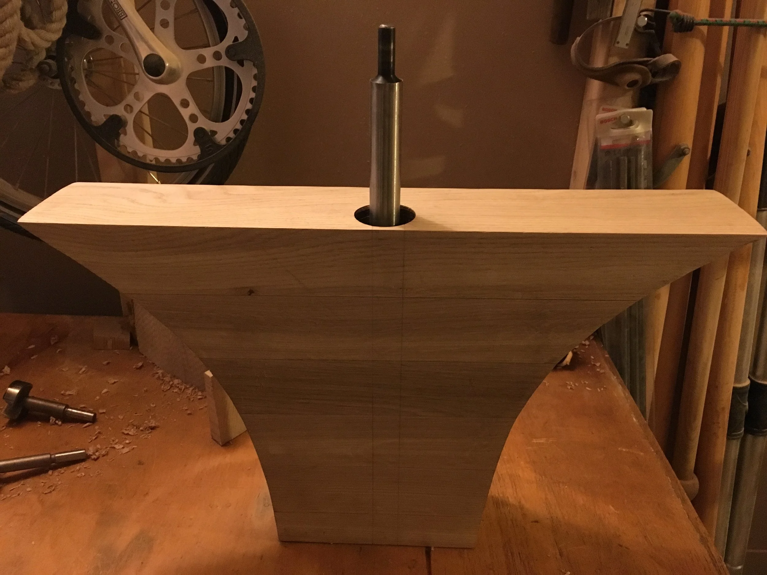
So the plan now is to install this floor timber with new keel bolt - once Björn is done with making them - and filling the void around it with thin West system epoxy. That should penetrate the wood and fill any gaps around the keel bolt, securing it in tight fit and isolating from acidic oak. To prevent the bolt from being permanently glued to the floor I will cover it with grease or wrap a thin foil around it. Once the epoxy cures I should be able to bang the bolt down into the keel timber.

What will I do differently with next floor timber?
Several things:

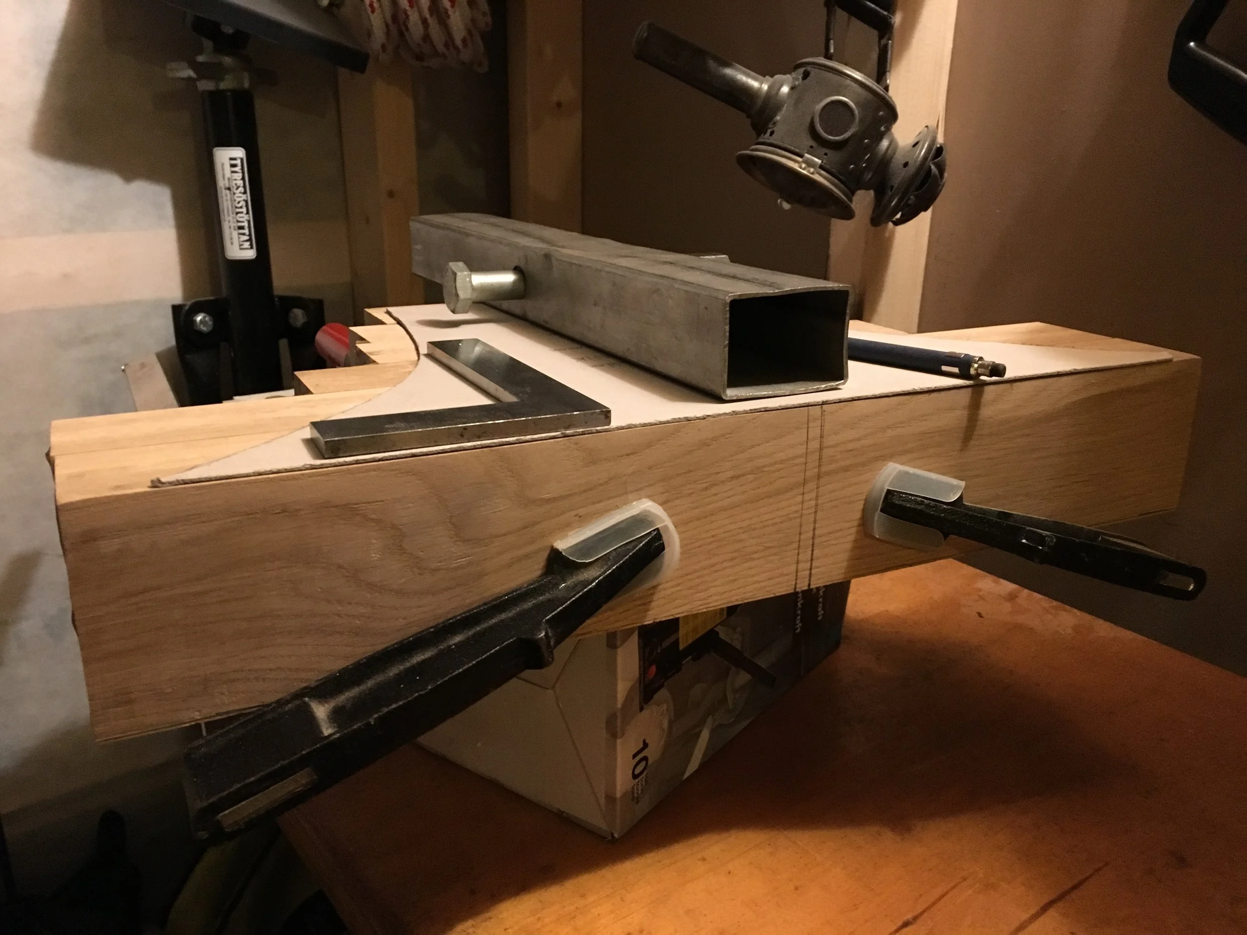
  • square and join the wood more carefully so that 4 faces are true and perpendicular. That should make it easier to align any jig or drilling aid

  • if I will use laminated construction, like in the current floor #3, I might fit all parts into bilge without prior gluing them. This will give me opportunity to drill shallow holes one-by-one. More work but seems safer

  • I will use wooden dowels to connect all parts after fitting and before gluing. That will prevent them from gliding during gluing and allow me to disassembly the stack for drilling on the drill press. Saves much time in post-treatment as the component will just need to be cleaned from hardened epoxy and not made square again

  • if I happen to be drilling through so thick timber again I will get myself proper drills for the job. Probably auger drills would be most suitable: https://www.fine-tools.com/fisch-schlangenbohrer.html

So now I move to another jobs on Meritaten. When keel bolts finally arrive and temperature allows for using epoxy resins I will install this floor to finish the job.

And if - although I doubt it - I manage with other scheduled repairs before spring I might re-make this floor timber. This time with better drilling accuracy.
If not - there is still next winter ahead.

February 13, 2019 /Lukasz Kumanowski
Comment
FullSizeRender.jpg

Floor #3 - final fitting

February 10, 2019 by Lukasz Kumanowski

It is still tricky to drive through this huge amount of melting snow and ice on the road but I was eager to try the floor timber assembly on Meritaten.

Besides - I was about to meet Jim who took over from Börje the big, beautiful Laurinkoster beside Meritaten.

Once I finally arrived I set up improvised workshop under the boat. As expected, the floor timber assembly was slightly too wide so I needed to gradually remove wood from some places for getting it fit nicely.

During last week I’ve prepared the bottom part with drilled 20mm hole, following my measurements and patterns. I’ve used a proper, heavy duty drill press for getting accurate positioning and angle.

IMG_5632.JPG

Now comes a moment of truth: does pre-drilled hole match the keel bolt hole on the boat.
Well, not too bad for flimsy cardboard patterns - I’ve missed by less than 1mm!

IMG_5641.JPG

That’s nothing to sweat about, I can adjust the position of final drilling through the whole timber to accommodate for that.

I could now move on to shaping the rest of the assembly. Pencil lines helped in guiding high-speed, aggressive grinder.

FullSizeRender-2.jpg

In the end I got snug fit but after a while I figured that it should not be too tight - after all, this component will also swell and expand during its lifetime. The last thing I want is that it pushes out the garboard and causes a leak!

The role of floor timber is to hold both sides of the hull together and transfer forces between frames (pulling up and away) and ballast keel (pulling down). It is attached to keel timber and ballast keel with keel bolt going thru it. It then holds garboard plank with bronze screws and frames which are cross-bolted with rivets or machine screws, also in bronze.
The bigger the floor the better it functions in distributing these huge loads.

Having that in mind I’ve shaped it little more so that I don’t need to hammer it down for tight fit. It should rest on keel timber and leave as small gap to the freeboards as possible. Inevitable air gaps will be closed by bedding compound during assembly - to inhibit moisture accumulation and resulting rot.

So finally it sits in its place!

View fullsize IMG_5644.JPG
View fullsize IMG_5645.JPG
View fullsize IMG_5646.JPG

What is left now is to glue the very bottom, pre-drilled part. Learning from experience of sliding wood blocks on slippery epoxy I’ve made 2 wooden dowels which act as guiding pins.

IMG_5653.JPG

The glue will set overnight and then, after final cleaning of the assembly, I will measure and drill keel bolt hole through the whole thing.

IMG_5654.JPG
February 10, 2019 /Lukasz Kumanowski
Comment
FullSizeRender-2.jpg

Floor #3 - cutting and shaping

February 05, 2019 by Lukasz Kumanowski

Before I build myself a proper woodworking bench - with pigs and side-vise - I need to improvise when holding big timber for plaining. Using some clamps and portable vise solves this problem although it is far from perfect.

After squaring and dimensioning the laminated floor #3 I could move on and transfer cardboard patterns onto the wood. Aligned against their top edge - with centre mark scribed before on the boat - they should hopefully reflect 3D shape of this piece.

IMG_5620.JPG

The reason for using top edge for alignment is that not only the sides are different but also the bottom, where it sits on oak keel, is tilted due to the hull shape. Top edge is really the only place where both faces can be referenced.

To transfer also keel bolt position I’ve used a wooden block with 20mm diameter hole as a template. It was aligned on the keel, with drill bit serving as a guide. Then the position of the block was transferred to front face of the floor pattern.

FullSizeRender.jpg

Having all that done I’ve transferred shapes onto wood. The very bottom wooden piece is not yet glued hence I still have the assembly clamped.

IMG_5621.JPG

Then to cutting! Bandsaw to which I have access is in poor condition so I decided to use my trusty jigsaw. The longest blade was just enough to bite through this oak. It was a tough job - with many stops to protect the machine - but finally I got the rough shape of the front (bigger) face.

FullSizeRender-3.jpg

I was cutting as close to the line as I dared - due to timber thickness the blade had a tendency to skew so I wanted to have some margins and not cut too much. Anyhow the back face is at least 5mm slimmer so there is still a lot of wood to be removed.

IMG_5625.JPG
IMG_5626.JPG

To clearly mark the edges of the back face I’ve chiseled a chamfer along the line. That should give me a clear mark when I start to remove the wood between both faces.

FullSizeRender-4.jpg

The bulk of the wood now needs to be removed. I’ve chosen non-sporty way and used angle grinder with 40-grit, aggressively cutting sanding paper. One needs to be very careful when using this tool - it bites through the oak like through butter - very easy to remove too much.

FullSizeRender-5.jpg

For fine-tuning the profile I use spokeshave and grinder with less aggressive paper.

Now it is time to go to the boat and try this piece.

Hopefully the weather will calm down a bit - right now it is too dangerous to drive due to huge amount of snow and ice on the roads.

FullSizeRender-6.jpg
February 05, 2019 /Lukasz Kumanowski
Comment
FullSizeRender-2.jpg
FullSizeRender.jpg

Cleanup!

January 31, 2019 by Lukasz Kumanowski

After sufficient time for epoxy curing I could move on to cleaning the composite.

This particular epoxy exhibits severe amine blush after curing so before I touched it with any tools I cleaned the whole assembly with decent amount of acetone. This shall prevent the “wax” (amine) from being taken deeper into wood when I start to further work on it.

Although it is said that acetone is not removing the blush completely (water and soap is recommended) I needed to use acetone since, in freezing temperatures in my workshop, I have no water available.

IMG_5604.JPG

I don’t want to use my hand tools on cured epoxy so instead I used my “el-cheapo” electric plane. This tool I got for free and it is a real piece of junk so I feel no regrets in further wasting it on such job.

Due to the fact that wood was floating during gluing I got a stack where all elements are shifted in different directions. Not a catastrophe since I’ve left them over-dimensioned but it caused me more work to remove so much material on both faces. It also caused that I no longer have any true face - nothing is square any more on this assembly.

I need to be smarter next time and make wooden guiding pins which will index all jointing faces and prevent any shifting.

IMG_5605.JPG

The next step is to square this up again and bring down to required 74mm thickness. That will be accomplished with hand planes again - much better control, no more wood dust and much more fun!

January 31, 2019 /Lukasz Kumanowski
Comment
  • Newer
  • Older

Powered by Squarespace