Boatworks

  • Main
  • Louve
  • Typewriters
  • Workshop
  • Meritaten
  • Glypto
  • Motoko
  • Inspirations
  • About
FullSizeRender.jpg

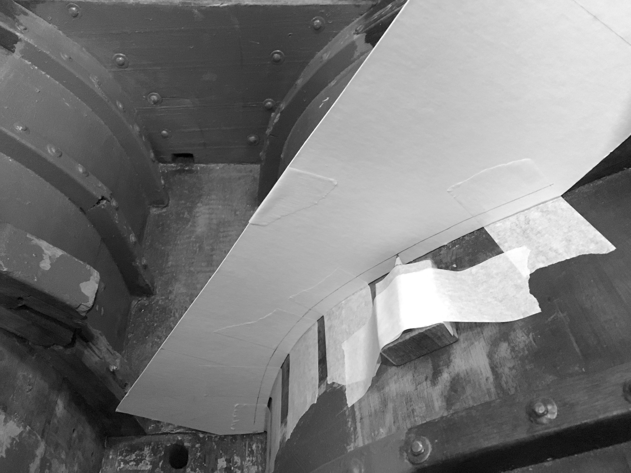
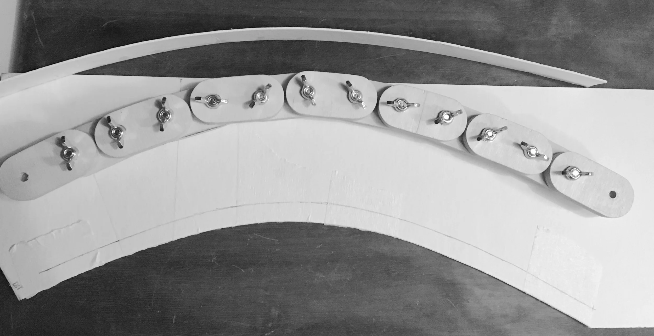
Reading timber patters - wood for Floor #3

January 20, 2019 by Lukasz Kumanowski

With floor timber patterns ready it was about time to prepare the wood.

First thing I did was to look closely onto annual growth rings pattern to determine best possible usage for my stock. I need not only to build floor #3 but also make laminated frames for repairing these which broke on Meritaten in tight bilge curve. If time and timber permits I’m also planning to make new frames for Glypto, my dinghy.

Having done that I’ve cut the stock into more manageable pieces of 1,5m - this oak is dense thus heavy so ripping it on portable table saw can be challenging at times.

Since my stock is live-edge plank - first I needed to remove bark and sapwood (lighter, less dense wood under the bark, used by the tree to transport water - hence prone to rot). I’ve ripped all planks on table saw and looked again onto what I got.

FullSizeRender-3.jpg

Apart from a considerable pile of firewood I got some nice material. I could now better determine which part will be used for frames and which goes into floor timber.

IMG_5518.JPG

One plank has tree’s heart in the middle. I’ve chosen it deliberately because that gives me quarter-sawn timber on both sides of the heart. Central part - with the heart - will have to be cut out as it is unstable and prone to checking. I will make my frames from these quarter-sawn parts.

FullSizeRender-4.jpg

The second plank is flat-sawn just above the tree heart - here I have a mixed grain since the tree was quite thin. I will use this stock to build my floor #3 - it will be laminated from circa 50mm thick pieces to make the total height.

FullSizeRender-5.jpg

Ideally floor timber should also be quarter-sawn if it was done from one piece. Very good explanation and guide about choosing wood fibres direction is given by Louis Sauzedde here: https://www.youtube.com/watch?v=dzCmES_Lwrs
Screen shot form Louis’ video below shows the ideal annual rings pattern for building floor timber.

Understanding wood grain and how to use it properly - REMORA (Part 5) Louis Sauzedde https://www.youtube.com/watch?v=dzCmES_Lwrs

Understanding wood grain and how to use it properly - REMORA (Part 5) Louis Sauzedde
https://www.youtube.com/watch?v=dzCmES_Lwrs

Since I don’t have such thick quarter-sawn stock I will build my floor in laminations - just as it was originally on my boat.

To glue oak with epoxy can be a challenge - I hope to dodge it with West system G-Flex epoxy which is specially formulated for gluing oak. Having wood pieces quite thin - 50 mm - should help the glue keeping them together and withstand swelling forces when moisture content will fluctuate. The glue itself allows up to 20% deformation without breaking the bond so it should do the job quite nicely.

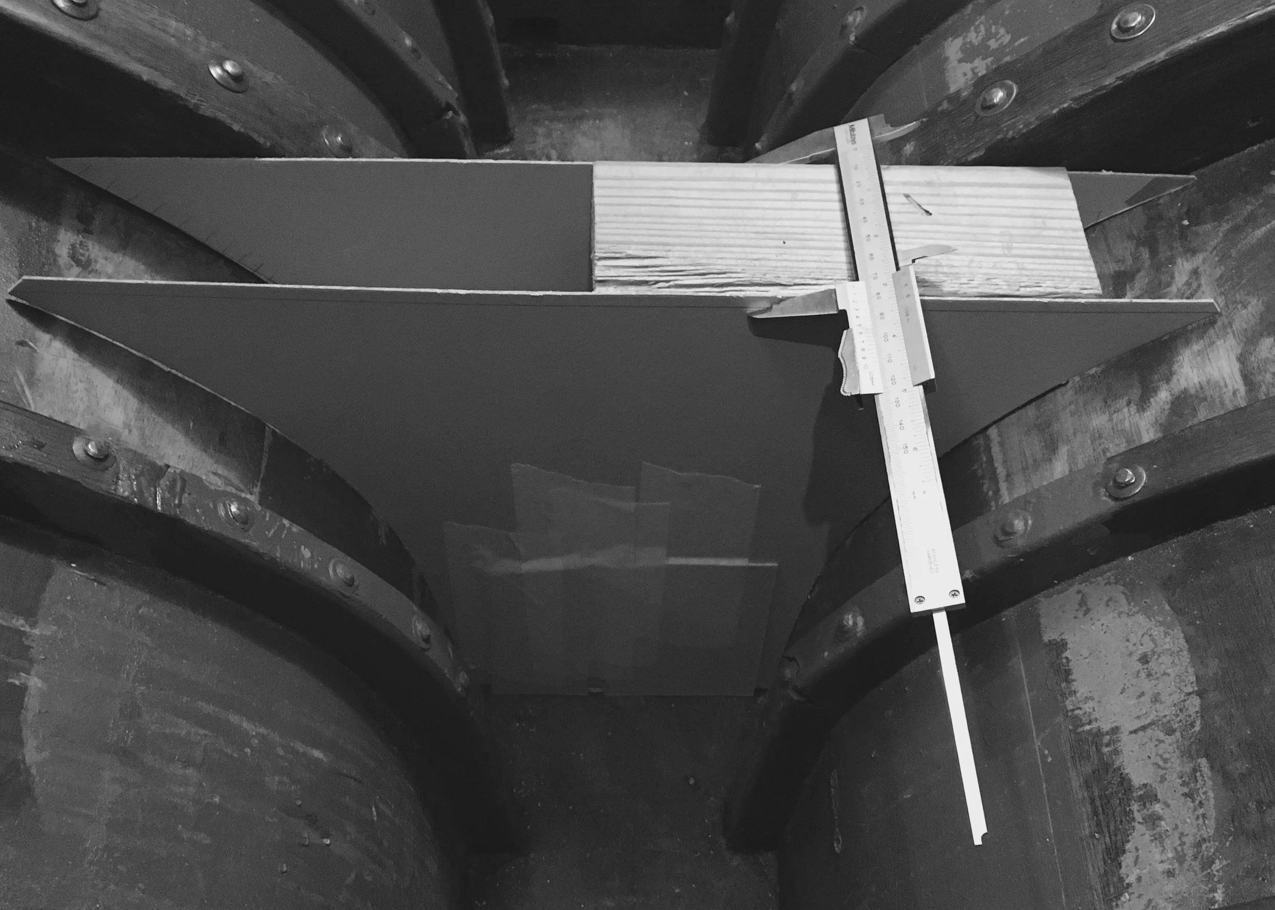
Next step now is to split my pattern into 50mm blocks, chose them from available stock, roughly-cut the wood and hand-plane to desired thickness/surface finish.

Since I will be using epoxy, which doesn’t like perfect face matching (gap filling property + glue starvation in too-good joints), I don’t have to make this extremely precise.
Wood-butcher level is enough for this.

January 20, 2019 /Lukasz Kumanowski
Comment

Tools of the trade

CAD - Cardboard Aided Design. Patterns for Floor #3

January 15, 2019 by Lukasz Kumanowski

There are a few methods to make a pattern of a compound shape: hot-glued sticks, spilling, chain pattern, shaped-stick pointer, scraps of cardboard etc. I use two of these - they compliment each other and are very quick.

First I use a wooden chain pattern to roughly determine the shape.

Chain lying on a cardboard batten - it works but it’s easier and more accurate to skip the batten at this stage.

Chain lying on a cardboard batten - it works but it’s easier and more accurate to skip the batten at this stage.

Most often chain alone is accurate enough to give me the exact curvature.

Having the chain locked I can now move it to a piece of cardboard and use a batten to record the shape. For this case I used cardboard batten as it was at hand.

FullSizeRender.jpg

Drawing a curve along flexed batten gives the curvature of the hull piece I’m replicating.

Sometimes - due to chain pattern not properly aligned or not tighten enough - the recorded shape is not exact but then more precise method - spilling - can be employed.

I use a short pencil attached to a wooden block with some tape. It is important to have a pencil in the middle of the block as it will pitch on the hull’s curvature.
Then - with steady hands and avoiding pitching and yawing - slide the pencil block along the curved surface, drawing its shape on the pattern.

Pencil on the wooden block. It’s good to wax the block to have smoother action against the hull’s curvature.

Pencil on the wooden block. It’s good to wax the block to have smoother action against the hull’s curvature.

The resulting shape would be very accurate - most of the time. If not - paper-tape shims can be applied to fill-in the curvature and obtain tight fit. After all - it is easier to work with cardboard and scissors than with oak so time spent on making exact pattern is well invested.

FullSizeRender-2.jpg

For floor timber I need to make four such patterns - two per each face. Since boat hull is a complex shape one needs to record not only hull’s curvature on one face but also rolling bevel which results in different shape on the other side of the timber. For me the easiest is to make patterns for both faces, align them and record on the new piece of wood to be cut into shape. Bevels will then - hopefully - result automatically from smooth meeting of these faces.

Resulting initial patterns are then aligned and I mark the top of the new piece with long, straight edge.

IMG_5496.JPG

I’ve decided to build this floor a little higher and have it wider. That will make it stronger ‘cause - as they say in Maine: nothing too strong ever broke.

The resulting final pattern is then cut in one-piece cardboard.

Front face of new floor timber, here with wooden pattern for keel bolt thru-hole.

Front face of new floor timber, here with wooden pattern for keel bolt thru-hole.

Now the same story for the second face. To have a proper alignment I’ve attached wooden blocks to have proper spacing of both faces.

Taking the shape of hull on the other side of new floor timber pattern

Taking the shape of hull on the other side of new floor timber pattern

Luckily shapes taken with wooden chain were spot-on this time so I could quickly produce both starboard and port sides.

FullSizeRender-6.jpg

As I will make this timber higher than others I can no longer directly determine the height of this pattern so I go ahead and cut it with excess cardboard on top.

FullSizeRender-7.jpg

Now, since the front-face pattern is already dimensioned to higher timber I can use straight edge and water level to mark my back-face pattern.

FullSizeRender-8.jpg

Cut to size and voila! The new 3D pattern is almost ready.

FullSizeRender-9.jpg

The new floor timber will be 74mm thick, instead of ca 59mm as in old floor.

FullSizeRender-10.jpg
FullSizeRender-11.jpg

What is left still is to tweak a bit some parts of the pattern to get perfect fit to hull and to record their relative position. Wooden pattern position for keel bolt placement needs also to be recorded on one of these faces.

Once I have that I can begin milling my stock of oak!

January 15, 2019 /Lukasz Kumanowski
Comment
FullSizeRender.jpg

Plane fun!

January 14, 2019 by Lukasz Kumanowski

I got few old wooden planes which were used by my grandfather and my father, occasionally. I’m especially excited about rabbet plane as I didn’t have one yet. The other plane is a mid-size bench plane, close to Stanley 4 size so I have it covered already with metal plane - but, in preparation for major rebuild work next season, I will modify this wooden plane to be convex-sole plane, for hollowing planks. The third plane I took from my father with aim of renovating it and giving back to him.

All these planes are in rough shape. They were nothing special in the days they were new - but they can work nicely and I like the idea of adjusting the plane iron with hammer taps. It is not difficult but not as straightforward as in metal planes where one has knobs for every adjustment. Here, in wooden planes, you need to get a feeling on where and how strong to tap for having iron adjusted as you need. Art in itself.

I started with rabbet plane.

FullSizeRender-6.jpg

First I wanted to clean and true the back side of the iron: it was rusty and seemed to be out of flat. Half an hour on 400-grit stone made the back of iron clean and flat enough to my taste. Polished a bit on 800 and 5000 stones and then moved to the beveled face.

Here it was a mess. First of all, the plane had only primary bevel, no micro-bevel for sharp edge. Measured angle was around 30 degrees so I’ve decided to grind down the primary bevel to the usual 25 degrees and then establish secondary micro-bevel 5 degrees higher, to 30 degrees.

Here I started to shape the primary bevel at 25 degrees

Here I started to shape the primary bevel at 25 degrees

It took almost 2 hours to finally grind all the way to the tip of this thick iron. At that point I could also clearly see that the iron is a lamination of two steel types: hardened top part which serves as a cutting edge and mild steel as backing - for strength and elasticity of the blade.

After grinding primary bevel the blade shows its structure of 2-part laminate

After grinding primary bevel the blade shows its structure of 2-part laminate

Once I got there I polished a bit the primary bevel on higher grade stones and then moved to producing micro-bevel for cutting edge.

While doing it I sharpened also my tiny and cheap hand plane. It’s really cheapo from Biltema by there is no reason to not have it sharp and ready for some small job.

FullSizeRender-4.jpg

The resulting edge is good enough for me: I could shave my hand with both irons. On rabbet plane iron I got some less-than-perfect face of secondary bevel, probably due to stone wear out or my fault during sharpening. I will correct it during next sharpening so no worries.

Still, compared to the other irons which wait in the queue these look pretty good.

“Before and after” study of shapes

“Before and after” study of shapes

Would I own Tormek T4 (or T8!) this job would take no more than 20 minutes. Maybe some day - but I find it difficult to justify so big expense while some spare time and elbow grease do the job just as well.
https://www.tormek.com/sweden/sv/maskinmodeller/tormek-t-4/

Next step for this plane is sole renovation - the wood is probably beechwood so nothing fancy like lignum vitae but hard enough to last.
I need to flatten the sole and true the sides against it. In this process the old finish will wear out - which is good because I will probably stain and then oil the wood, to have it satin and more pleasant for hands.

Dents from nails or misuse will need to be repaired with Dutchman-pieces. I have some nice beechwood in the workshop so it will have some good use here!

FullSizeRender-7.jpg


January 14, 2019 /Lukasz Kumanowski
2 Comments
FullSizeRender.jpg

Keel bolts - summary

January 13, 2019 by Lukasz Kumanowski

Well, after one month of fighting I got 3 keel bolts out.

Two of them went out pretty easy - they were in bad condition but oak layers through which they pass were not that thick.

Third one gave me lots of trouble due to deadwood through which it passed. Deterioration and rust expansion has caused it to really sit well, to the extent that it was impossible to remove it by simply pulinig it out inside the boat. Instead I was forced to take it in parts through keel opening pocket.

What would I do differently?

For such a nasty case I would try pulling it slower than I did, applying heat on the top part while pulling. This would make the metal expand and after cooling down hopefully the channel in oak and rust slug would get enlarged enough to enable extraction without breaking it.
To further increase odds I would maybe try cooling down the iron by applying -55 C spray in periods of pulling. Maybe it would yield metal more britle and prone to breaking but I don’t think the bolt will really go down to -55 degrees C. Worth trying but risky.

Then, if the bolt breaks upon pulling I would hammer it down again, as I did. It proved that the channel behind the bolt was already wide enough to accommodate the bolt. And yes, I would first drill pilot hole into the bolt’s core to inhibit mushroom effect inevitable with hard hammering.
Drilling through the bolt is tedious and very time consuming. Should I be forced to go this way all along I would build a jig for holding the drill steady and straight, with enough pressure to enable milling but without my assistance. Then I could leave it for few hours and come back to change the battery and replenish drilling oil.

The budget, not counting men-hours, became also stretched. That is mainly due to the lead being poured into keel pockets instead of being hammered in. That closed the option of drilling and tapping the lead plug and extraction with hydraulic jacks. Instead I had to melt it away - investing in new tools (which is cool but costs) and several bottles of gases.

FullSizeRender-2.jpg

So how do I proceed from here?

I’m considering enlarging keel bolts to 20mm metric. That would give me more options in steel rods which, in Europe, are manufactured mostly in 18, 20, 22mm etc. To get the same, 3/4 inch diameter I am limited to tool steel (silver steel) which comes in 19mm diameter - with very tight tolerances. That makes it costly.
Besides - oak in keel bolt channels is deteriorated by iron sickness. Drilling it out to 20mm diameter will expose fresh(er) wood and rusting of new keel bolts will proceed slower - at least I hope.
The only question is how long will it take to re-drill iron casted ballast keel.

I’m meeting my machinist expert this week so then we will decide how to proceed.

For lead plugs I’ve already decided to cast them into properly-sized bricks which then will be hammered into keel pockets and faired with epoxy for smoothing-up the surface. I don’t want to melt them to extract keel bolts next time!

January 13, 2019 /Lukasz Kumanowski
3 Comments
FullSizeRender-2.jpg

Keel bolt #3 - Final extraction

January 10, 2019 by Lukasz Kumanowski

With electricity back in the boatyard work became more pleasant.

I continue cutting pieces of the keel bolt down in the tight ballast keel pocket. No normal saw can reach there. Neither reciprocating saw. The only possible way to saw the bolt would be with garota-style saw, like the one used in movies about prison escapes.

I’ve made one to give it a try. It broke almost instantly.

FullSizeRender.jpg

As I don’t dare to use acetylene torch here my only option was to continue with drilling holes in the bolt and then cutting remaining metal witch chisel and hammer.
It was a tough fight. Situation was even more difficult since the bolt now could turn on its axis, making drilling very tricky.

IMG_5470.JPG

Finally, the last bit was out. Job is done!

The long waited moment that I see light through keel timber, deadwood and iron ballast has finally came!

IMG_5472.JPG


What is left now is to drill the remaining oxide slug to clean all three holes, measure the length of keel bolt #3 required and contacting Björn for manufacturing all three new bolts.

And, of course, building new floors from fresh oak!
Finally - back to wood working!

January 10, 2019 /Lukasz Kumanowski
Comment
  • Newer
  • Older

Powered by Squarespace